FRONT SUSPENSION MEMBER (for Sedan) > INSTALLATION |

for Preparation Click here
| 1. INSTALL ENGINE MOVING CONTROL ROD |
Install the engine moving control rod with the bolt.
- Torque:
- 100 N*m{ 1020 kgf*cm , 74 ft.*lbf }
- HINT:
- Temporarily tighten the transaxle side, and then tighten the bolt to the specified torque.
| 2. INSTALL ENGINE MOVING CONTROL ROD COVER (for Cold Area) |
Install the engine moving control rod cover with the 2 clips.
| 3. TEMPORARILY TIGHTEN FRONT LOWER SUSPENSION ARM SUB-ASSEMBLY LH |
Provisionally tighten the lower arm with the 2 bolts.
Install the lower arm to the steering knuckle with a new castle nut.
- Torque:
- 98 N*m{ 1000 kgf*cm , 72 ft.*lbf }
- NOTICE:
- If the holes for the clip are not aligned, tighten the nut by a further turn of up to 60°.
 |
Install a new clip.
| 4. TEMPORARILY TIGHTEN FRONT LOWER SUSPENSION ARM SUB-ASSEMBLY RH |
- HINT:
- Use the same procedure for the RH side as for the LH side.
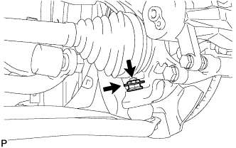
| 5. INSTALL FRONT STABILIZER BAR |
| 6. INSTALL FRONT STABILIZER BRACKET LH |
 |
Provisionally tighten bolt A.
Tighten the bolts to the specified torque, in the order of B then A.
- Torque:
- 47 N*m{ 479 kgf*cm , 35 ft.*lbf }
| 7. INSTALL FRONT STABILIZER BRACKET RH |
- HINT:
- Use the same procedure for the RH side as for the LH side.
| 8. INSTALL STEERING GEAR ASSEMBLY |
Install the steering gear assembly onto the front suspension crossmember with the 2 bolts and 2 nuts.
- Torque:
- 79 N*m{ 800 kgf*cm , 58 ft.*lbf }
- NOTICE:
- Keep the nut from rotating while turning the bolt.
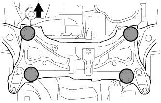
| 9. INSTALL FRONT SUSPENSION CROSSMEMBER SUB-ASSEMBLY |
Place wooden blocks or plate lift attachments on an engine lifter, and then set the front suspension crossmember sub-assembly so that the attachments are in the positions shown in the illustration.
Text in Illustration 
Front of the Vehicle 
Attachment Placement Positions
 |
Temporarily install the front suspension crossmember sub-assembly to the body with the 6 bolts.
By inserting SST into the datum holes in the front suspension crossmember RH and LH alternately, tighten bolts A, B and C on both sides to the specified torque, in several steps.
- SST
- 09670-00011
- Torque:
- Bolt A:
- 87 N*m{ 887 kgf*cm , 64 ft.*lbf }
- Bolt B:
- 151 N*m{ 1540 kgf*cm , 111 ft.*lbf }
- Bolt C:
- 98 N*m{ 999 kgf*cm , 72 ft.*lbf }
- NOTICE:
- Insert SST into the datum hole in a vertical orientation.
- If SST cannot be inserted into the datum hole vertically, loosen all the bolts and then insert SST again.
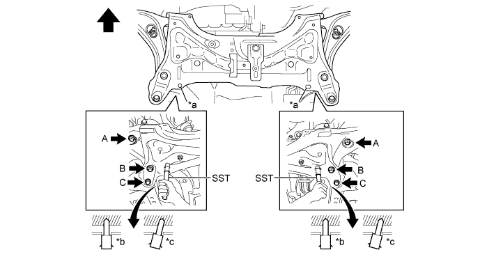
Text in Illustration *a Datum Hole *b OK *c NG - - Front of the Vehicle - -
Install the engine moving control rod with the bolt.
- Torque:
- 120 N*m{ 1224 kgf*cm , 89 ft.*lbf }
| 10. INSTALL FRONT LOWER SUSPENSION ARM SUB-ASSEMBLY LH |
Install the front lower suspension arm sub-assembly LH to the steering knuckle with a new castle nut.
- Torque:
- 98 N*m{ 999 kgf*cm , 72 ft.*lbf }
- NOTICE:
- If the holes for the clip are not aligned, tighten the nut by a further turn of up to 60°.
Install a new clip.
| 11. INSTALL FRONT LOWER SUSPENSION ARM SUB-ASSEMBLY RH |
- HINT:
- Use the same procedure for the RH side as for the LH side.
| 12. INSTALL TIE ROD END SUB-ASSEMBLY LH |
Install the tie rod end sub-assembly LH to the steering knuckle with a new castle nut.
- Torque:
- 49 N*m{ 500 kgf*cm , 36 ft.*lbf }
- NOTICE:
- If the holes for the clip are not aligned, tighten the nut by a further turn of up to 60°.
Install a new cotter pin.
| 13. INSTALL TIE ROD END SUB-ASSEMBLY RH |
- HINT:
- Use the same procedure for the RH side as for the LH side.
| 14. INSTALL FRONT STABILIZER LINK ASSEMBLY LH |
Install the front stabilizer link assembly LH with the nut.
- Torque:
- 74 N*m{ 755 kgf*cm , 55 ft.*lbf }
- HINT:
- If the ball joint turns together with the nut, use a socket hexagon wrench 6 mm to hold the stud.
| 15. INSTALL FRONT STABILIZER LINK ASSEMBLY RH |
- HINT:
- Use the same procedure for the RH side as for the LH side.
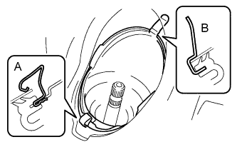
| 16. INSTALL NO. 1 STEERING COLUMN HOLE COVER SUB-ASSEMBLY |
Install clip B to the body portion and install the No. 1 steering column hole cover sub-assembly to the body portion with clip A.
- NOTICE:
- Make sure that the lip portion of steering column hole cover is not damaged.
 |
| 17. INSTALL STEERING SLIDING YOKE SUB-ASSEMBLY |
Align the matchmarks and install the steering sliding yoke sub-assembly to the power steering gear.
Text in Illustration *1 Steering Sliding Yoke Sub-assembly *a Matchmark
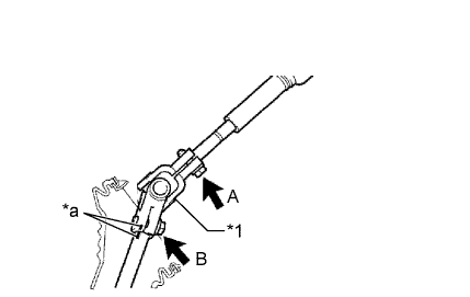 |
Install bolt B.
- Torque:
- 35 N*m{ 360 kgf*cm , 26 ft.*lbf }
Tighten bolt A.
- Torque:
- 35 N*m{ 360 kgf*cm , 26 ft.*lbf }
| 18. INSTALL COLUMN HOLE COVER SILENCER SHEET |
Install the column hole cover silencer sheet with the 2 clips.
Install the floor carpet.
| 19. INSTALL FRONT WHEEL |
- Torque:
- 103 N*m{ 1050 kgf*cm , 76 ft.*lbf }
| 20. POSITION FRONT WHEELS FACING STRAIGHT AHEAD |
| 21. STABILIZE SUSPENSION |
Lower the vehicle.
Bounce the vehicle up and down several times to stabilize the suspension.
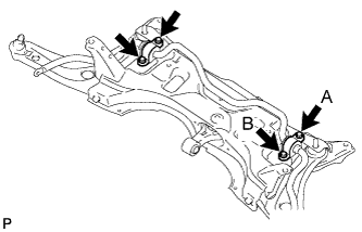
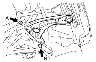
| 22. FULLY TIGHTEN FRONT LOWER SUSPENSION ARM SUB-ASSEMBLY LH |
Fully tighten the 2 bolts.
- Torque:
- Bolt A:
- 137 N*m{ 1397 kgf*cm , 101 ft.*lbf }
- Bolt B:
- 151 N*m{ 1540 kgf*cm , 111 ft.*lbf }
 |
| 23. FULLY TIGHTEN FRONT LOWER SUSPENSION ARM SUB-ASSEMBLY RH |
- HINT:
- Use the same procedure for the RH side as for the LH side.
| 24. INSPECT AND ADJUST FRONT WHEEL ALIGNMENT |
| 25. CHECK ABS SENSOR SIGNAL |