FRONT SUSPENSION MEMBER (for Hatchback) > REMOVAL |

for Preparation Click here
| 1. POSITION FRONT WHEELS FACING STRAIGHT AHEAD |
| 2. REMOVE COLUMN HOLE COVER SILENCER SHEET |
Remove the 2 clips and the column hole cover silencer sheet.
 |
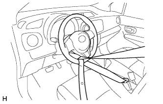
| 3. SEPARATE STEERING SLIDING YOKE SUB-ASSEMBLY |
Use a seat belt to fix the steering wheel assembly, in order to avoid breakage of the spiral cable.
 |
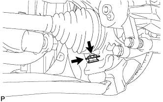
Place matchmarks on the steering sliding yoke sub-assembly and the steering gear assembly.
Text in Illustration *1 Steering Sliding Yoke Sub-assembly *a Matchmark
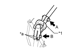 |
Loosen bolt A, remove bolt B and separate the steering sliding yoke sub-assembly from the steering gear assembly.
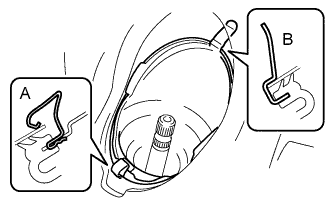
| 4. SEPARATE NO. 1 STEERING COLUMN HOLE COVER SUB-ASSEMBLY |
Remove clip A, separate clip B from the body and separate the No. 1 steering column hole cover sub-assembly.
- NOTICE:
- Do not damage clip B.
 |
| 5. REMOVE FRONT WHEEL |
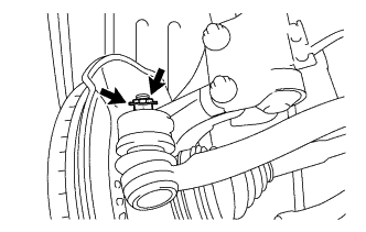
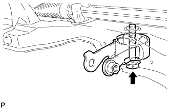
| 6. SEPARATE FRONT STABILIZER LINK ASSEMBLY LH |
Remove the nut and separate the stabilizer link assembly LH from the front stabilizer bar.
- HINT:
- Using a socket hexagon wrench 6 to hold the stud.
 |
| 7. SEPARATE FRONT STABILIZER LINK ASSEMBLY RH |
- HINT:
- Use the same procedure for the RH side as for the LH side.
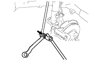
| 8. SEPARATE TIE ROD END SUB-ASSEMBLY LH |
Remove the cotter pin and the castle nut.
 |
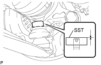
Install SST to the threaded section of the tie rod end sub-assembly.
- SST
- 09960-20010
(09961-02060)
- NOTICE:
- Make sure the upper ends of the threaded section of the tie rod end and SST are aligned.
 |
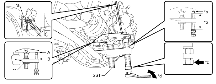
Using SST, separate the tie rod end sub-assembly from the front axle assembly.
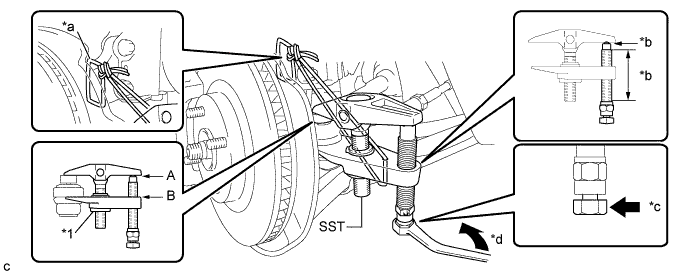
Text in Illustration *1 Center Nut - - *a String *b Molybdenum Grease Application Area *c Place the wrench here *d Turn - SST
- 09960-20010
(09961-02010)
- NOTICE:
- Apply molybdenum grease to the bolt threads and the tip of SST.
- Make sure to tie the string of SST to the vehicle to prevent SST from dropping.
- Install SST so that A and B are parallel.
- Be sure to place the wrench on the part indicated in the illustration.
- Do not damage the ball joint dust cover.
- Do not damage the front disc brake dust cover.
| 9. SEPARATE TIE ROD END SUB-ASSEMBLY RH |
- HINT:
- Use the same procedure for the RH side as for the LH side.
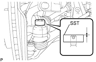
| 10. SEPARATE FRONT LOWER SUSPENSION ARM SUB-ASSEMBLY LH |
Remove the clip and the castle nut.
 |
Install SST to the threaded section of the lower ball joint.
- SST
- 09960-20010
(09961-02060)
- NOTICE:
- Make sure the upper ends of the threaded section of the lower ball joint and SST are aligned.
 |
Using SST, separate the front lower suspension arm from the front axle assembly.
Text in Illustration *1 Center Nut - - *a String *b Molybdenum Grease Application Area *c Place the wrench here *d Turn - SST
- 09960-20010
(09961-02010)
- NOTICE:
- Apply molybdenum grease to the bolt threads and the tip of SST.
- Make sure to tie the string of SST to the vehicle to prevent SST from dropping.
- Install SST so that A and B are parallel.
- Be sure to place the wrench on the part indicated in the illustration.
- Do not damage the lower ball joint dust cover.
- Do not damage the drive shaft outboard joint boots.
- Do not damage the front disc brake dust cover.
| 11. SEPARATE FRONT LOWER SUSPENSION ARM SUB-ASSEMBLY RH |
- HINT:
- Use the same procedure for the RH side as for the LH side.
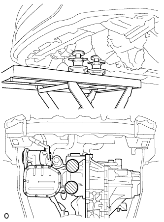
| 12. SUSPEND ENGINE ASSEMBLY (for Automatic Transaxle) |
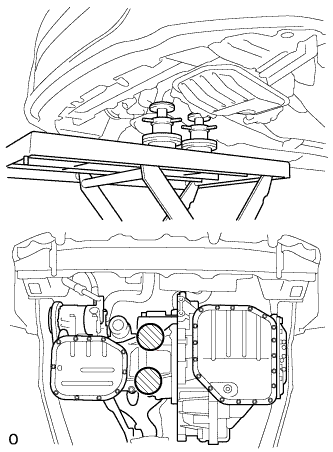
On a flat location, set the attachment, plate lift attachment, and wooden block in the positions shown in the figure, and set the engine assembly.
Text in Illustration 
Attachment Placement Positions - NOTICE:
- Set the engine assembly with transaxle so that it is horizontal.
- Never attach the attachment and plate lift attachment to the oil pan section of the automatic transaxle.
 |
| 13. SUSPEND ENGINE ASSEMBLY (for Manual Transaxle) |
On a flat location, set the attachment, plate lift attachment, and wooden block in the positions shown in the figure, and set the engine assembly.
Text in Illustration Attachment Placement Positions - NOTICE:
- Set the engine assembly with transaxle so that it is horizontal.
- Never attach the attachment and plate lift attachment to the oil pan section of the manual transaxle.
 |
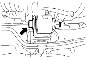
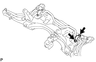
| 14. REMOVE FRONT SUSPENSION CROSSMEMBER SUB-ASSEMBLY |
Remove the bolt and separate the engine moving control rod.
 |
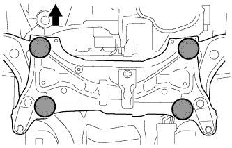
Place wooden blocks or plate lift attachments in the positions shown in the illustration and set an engine lifter underneath the front suspension crossmember sub-assembly.
Text in Illustration 
Front of the Vehicle 
Attachment Placement Positions - NOTICE:
- Place the wooden blocks or plate lift attachments so that the front suspension crossmember sub-assembly is level.
- As the front suspension crossmember sub-assembly is very heavy, be sure to support it securely.
 |
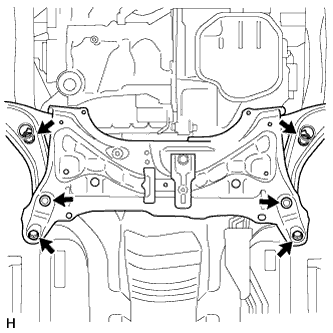
Remove the 6 bolts and front suspension crossmember sub-assembly.
 |
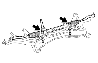
| 15. REMOVE MANUAL STEERING GEAR |
Remove the 2 bolts, 2 nuts and the manual steering gear from the front suspension crossmember.
- NOTICE:
- Keep the nut from rotating while turning the bolt.
 |
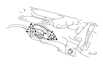
| 16. REMOVE FRONT NO. 1 STABILIZER BRACKET LH |
Remove the 2 bolts and the front No. 1 stabilizer bracket LH.
 |
| 17. REMOVE FRONT NO. 1 STABILIZER BRACKET RH |
- HINT:
- Use the same procedure for the RH side as for the LH side.
| 18. REMOVE FRONT STABILIZER BAR |
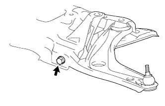
| 19. REMOVE FRONT LOWER SUSPENSION ARM SUB-ASSEMBLY LH |
Remove the bolt and the front lower suspension arm sub-assembly LH.
 |
| 20. REMOVE FRONT LOWER SUSPENSION ARM SUB-ASSEMBLY RH |
- HINT:
- Use the same procedure for the RH side as for the LH side.
| 21. REMOVE ENGINE MOVING CONTROL ROD COVER (for Cold Area) |
Remove the 2 clips and the engine moving control rod cover.
 |
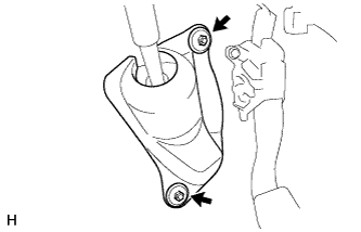
| 22. REMOVE ENGINE MOVING CONTROL ROD |
Remove the bolt and the engine moving control rod.
 |