ANTI-LOCK BRAKE SYSTEM (for Sedan) > TC and CG Terminal Circuit |

for Preparation Click here
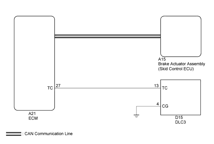
DESCRIPTION
Connecting terminals TC and CG of the DLC3 causes the ECU to display the DTC by blinking the ABS warning light.WIRING DIAGRAM
- HINT:
- When the warning lights continue to blink, there may be a ground short in the wiring of terminal TC of the DLC3 or an internal ground short in one or more ECUs.
INSPECTION PROCEDURE
| 1.CHECK CAN COMMUNICATION SYSTEM |
Check if CAN communication system DTCs are output (Click here).
Result Result Proceed to DTC is not output A DTC is output B
|
| ||||
| A | |
| 2.INSPECT DLC3 |
Turn the ignition switch to ON.
 |
Measure the voltage according to the value(s) in the table below.
- Standard Voltage:
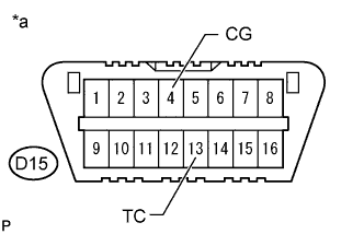
Tester Connection Switch Condition Specified Condition D15-13 (TC) - D15-4 (CG) Ignition switch ON 11 to 14 V
Text in Illustration *a Front view of DLC3 Result Result Proceed to NG A OK B
|
| ||||
| A | |
| 3.CHECK HARNESS AND CONNECTOR (TC of DLC3 - ECM) |
Turn the ignition switch off.
Disconnect the A21 ECM connector.
Measure the resistance according to the value(s) in the table below.
- Standard Resistance:
Tester Connection Condition Specified Condition D15-13 (TC) - A21-27 (TC) Always Below 1 Ω D15-13 (TC) - Body ground Always 10 kΩ or higher
Reconnect the A58 ECM connector.
|
| ||||
| OK | |
| 4.CHECK HARNESS AND CONNECTOR (CG of DLC3 - BODY GROUND) |
Measure the resistance according to the value(s) in the table below.
- Standard Resistance:
Tester Connection Condition Specified Condition D15-4 (CG) - Body ground Always Below 1 Ω
|
| ||||
| OK | |
| 5.INSPECT ECM (TC of DLC3 INPUT) |
- SST
- 09843-18040
Turn the ignition switch off.
|
Using SST, connect terminals TC and CG of the DLC3.
Turn the ignition switch to ON.
Check that the Malfunction Indicator Lamp (MIL) is blinking.
Text in Illustration *a Front view of DLC3 Result Result Proceed to Malfunction Indicator Lamp (MIL) is blinking A Malfunction Indicator Lamp (MIL) is not blinking B
|
| ||||
| A | ||
| ||