REAR AXLE BEAM (for Sedan) > INSTALLATION |

for Preparation Click here
| 1. INSTALL REAR AXLE CARRIER BUSH LH |
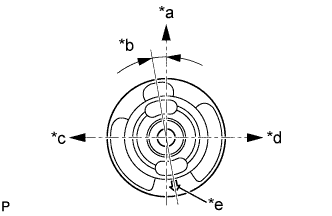
Align the matchmarks on a new bush and the axle beam and temporarily install the bush to the axle beam, as shown in the illustration.
Text in Illustration *a Upper Side *b 7 to 13° *c Front Side *d Rear Side *e Alignment Mark - NOTICE:
- Install the bush in the same orientation as the old one was prior to removal because they are directional.
 |
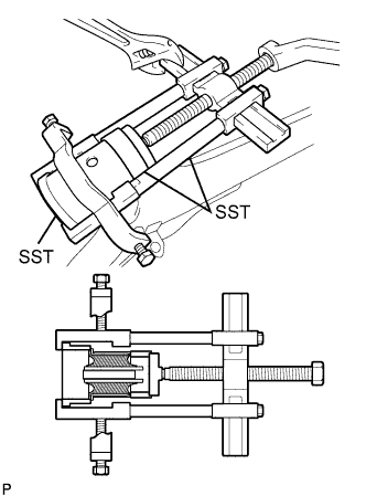
Using SST, install the bush to the axle beam.
- SST
- 09950-40011
(09951-04020, 09952-04010, 09953-04030, 09954-04030, 09955-04051, 09957-04010, 09958-04011)
09950-60020 (09951-00810)
09387-02010
09223-15020
- NOTICE:
- Do not damage the rubber portion when installing the bush.
 |
| 2. INSTALL REAR AXLE CARRIER BUSH RH |
- HINT:
- The installation procedure for the RH side is the same as that for the LH side.
| 3. TEMPORARILY TIGHTEN REAR AXLE BEAM |
Support the rear axle beam with a jack.
Install the axle beam to the vehicle and temporarily tighten the 2 bolts.
| 4. INSTALL REAR COIL SPRING LH |
Install the coil spring insulator lower to the axle beam.
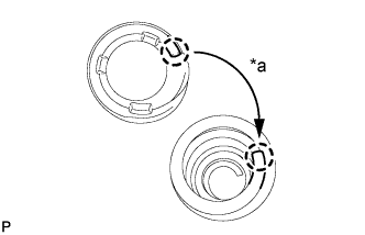
Install the coil spring insulator upper so that its gap fits to the end of coil spring.
Text in Illustration *a Fit
 |
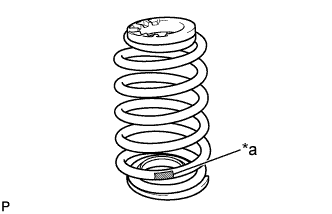
Install the coil spring to the axle beam.
Text in Illustration *a Paint Mark - NOTICE:
- The paint mark of the coil spring should be towards the underside and rear side of the vehicle.
 |
| 5. INSTALL REAR COIL SPRING RH |
- HINT:
- The installation procedure for the RH side is the same as that for the LH side.
| 6. TEMPORARILY TIGHTEN REAR SHOCK ABSORBER LH |
Support the axle beam with a jack. Insert a wooden block between the jack and the rear axle spring seat to prevent damage.
Jack up the axle beam slowly, and provisionally tighten the shock absorber (lower side) with the bolt and nut to the axle beam.
Install the suspension support and cushion retainer.
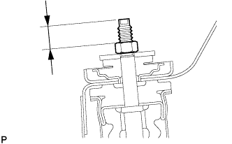
While holding the piston rod, install a new nut (lower nut) to the specified standard.
- Standard:
- 15 to 18 mm (0.591 to 0.709 in.)
 |
Hold the lower nut and tighten the upper nut against it.
- Torque:
- 25 N*m{ 250 kgf*cm , 18 ft.*lbf }
| 7. TEMPORARILY TIGHTEN REAR SHOCK ABSORBER RH |
- HINT:
- The installation procedure for the RH side is the same as that for the LH side.
| 8. INSTALL REAR AXLE HUB AND BEARING ASSEMBLY LH |
Install the axle hub and bearing to the axle beam with the 4 bolts.
- Torque:
- 90 N*m{ 918 kgf*cm , 67 ft.*lbf }
| 9. INSTALL REAR AXLE HUB AND BEARING ASSEMBLY RH |
- HINT:
- The installation procedure for the RH side is the same as that for the LH side.
| 10. INSPECT REAR AXLE HUB BEARING |
 |
Inspect the axle hub and bearing backlash.
Using a dial indicator, check the backlash near the center of the axle hub.
- Maximum:
- 0.05 mm (0.0020 in.)
Inspect the axle hub and bearing runout.
Using a dial indicator, check the runout of the surface of the axle hub.
- Maximum:
- 0.07 mm (0.0028 in.)
 |
| 11. INSTALL REAR BRAKE DRUM SUB-ASSEMBLY |
| 12. ADJUST REAR DRUM BRAKE SHOE CLEARANCE |
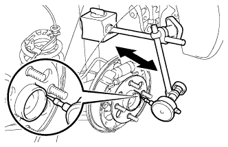
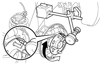
Provisionally install the 2 hub nuts.
Remove the hole plug, and turn the adjuster to expand the shoe until the drum locks.
Text in Illustration *1 Automatic Adjust Lever 
Expand
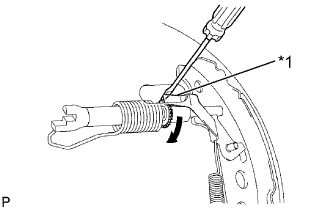 |
Using a screwdriver, release the adjuster 12 notches.
Install the hole plug.
| 13. INSTALL NO. 3 PARKING BRAKE CABLE ASSEMBLY |
Install the parking brake cable with the bolt and a new clamp.
- Torque:
- 6.0 N*m{ 61 kgf*cm , 53 in.*lbf }
| 14. INSTALL NO. 2 PARKING BRAKE CABLE ASSEMBLY |
- HINT:
- The installation procedure for the RH side is the same as that for the LH side.
| 15. INSTALL REAR NO. 4 BRAKE TUBE |
Install the brake tube to the axle beam with the nut.
- Torque:
- 5.0 N*m{ 51 kgf*cm , 44 in.*lbf }
Connect the flexible hose to the axle beam with a new clip.
Using a union nut wrench 10 mm, install the brake tube while holding the flexible hose with a wrench.
- Torque:
- 15 N*m{ 155 kgf*cm , 11 ft.*lbf }
- NOTICE:
- Use the formula to calculate special torque values for situations where the union nut wrench is combined with a torque wrench (Click here).
| 16. INSTALL REAR NO. 3 BRAKE TUBE |
- HINT:
- The installation procedure for the RH side is the same as that for the LH side.
| 17. INSTALL SKID CONTROL SENSOR WIRE (w/ ABS) |
Install the skid control sensor wire to the axle beam with the nut.
- Torque:
- 6.0 N*m{ 61 kgf*cm , 53 in.*lbf }
Connect the skid control sensor wire connector.
| 18. INSTALL REAR WHEEL |
- Torque:
- 103 N*m{ 1050 kgf*cm , 76 ft.*lbf }
| 19. STABILIZE SUSPENSION |
Lower the vehicle from the jack.
Bounce the vehicle up and down several times to stabilize the suspension.
| 20. FULLY TIGHTEN REAR AXLE BEAM |
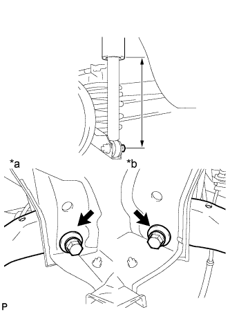 |
Suspend the jack on the rear axle spring seat and adjust the length of the shock absorber to the reference value.
Text in Illustration *a RH Side *b LH Side - Length of shock absorber:
- 220 mm (8.66 in.)
Fully tighten the 2 bolts.
- Torque:
- 90 N*m{ 918 kgf*cm , 67 ft.*lbf }
| 21. FULLY TIGHTEN REAR SHOCK ABSORBER LH |
Fully tighten the shock absorber (lower side) with the bolt.
- Torque:
- 49 N*m{ 500 kgf*cm , 36 ft.*lbf }
| 22. FULLY TIGHTEN REAR SHOCK ABSORBER RH |
- HINT:
- The installation procedure for the RH side is the same as that for the LH side.
| 23. INSTALL REAR SEATBACK ASSEMBLY (for Fixed Seat Type) |
Engage the 3 hooks and install the rear seatback.
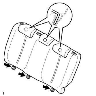 |
Tighten the 3 bolts.
- Torque:
- 7.9 N*m{ 80 kgf*cm , 70 in.*lbf }
Install the rear seat outer belt into the rear seat shoulder belt guide.
- HINT:
- Use the same procedure for both sides.
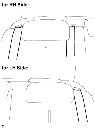 |
Install the rear center seat outer belt into the rear center seat shoulder belt guide.
| 24. INSTALL REAR SEAT CUSHION COVER PAD SUB-ASSEMBLY (for Fixed Seat Type) |
Pass the rear seat inner belt through the rear seat cushion cover pad slit.
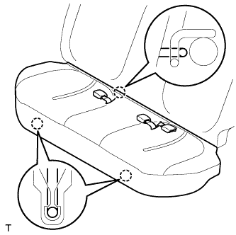 |
Engage the 3 hooks and install the rear seat cushion cover pad.
- NOTICE:
- Make sure that the 2 rear seat cushion lock hooks and the rear seat cushion frame are securely engaged.
| 25. FILL RESERVOIR WITH BRAKE FLUID |
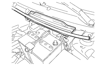 |
Disengage the 3 clips and separate the hood to cowl top seal.
Remove the cowl top ventilator louver.
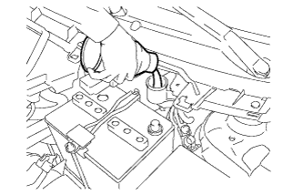
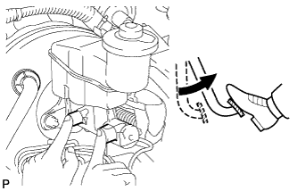
Set the brake fluid can upside down on the reservoir.
- Fluid:
- SAE J1703 or FMVSS No. 116 DOT3
 |
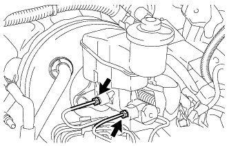
| 26. BLEED MASTER CYLINDER |
- HINT:
- If the master cylinder has been disassembled or if the reservoir becomes empty, bleed the air from the master cylinder.
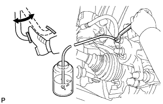
Using a 10 mm union nut wrench, disconnect the 2 brake tubes from the master cylinder.
 |
Slowly depress the brake pedal and hold it there (Step A).
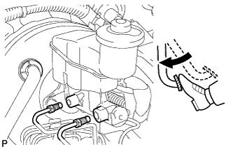 |
Block the outer holes with your fingers, and release the brake pedal (Step B).
 |
Repeat step A and B 3 or 4 times.
Using a 10 mm union nut wrench, connect the 2 brake tubes to the master cylinder.
- Torque:
- 15 N*m{ 155 kgf*cm , 11 ft.*lbf }
- NOTICE:
- Use the formula to calculate special torque values for situations where a union nut wrench is combined with a torque wrench (Click here).
|
| 27. BLEED BRAKE LINE |
 |
Connect the vinyl tube to the bleeder plug.
Depress the brake pedal several times, then loosen the bleeder plug with the pedal depressed (Step C).
At the point where the fluid stops coming out, tighten the bleeder plug, then release the brake pedal (Step D).
Repeat step C and D until all the air in the fluid is completely bled out.
Tighten the bleeder plug.
- Torque:
- 8.3 N*m{ 85 kgf*cm , 73 in.*lbf }
Repeat the above procedure to bleed the air out of the brake line for each wheel.
| 28. INSPECT FLUID LEVEL IN RESERVOIR |
Check the fluid level and add fluid if necessary.
- Fluid:
- SAE J1703 or FMVSS No. 116 DOT3
| 29. INSPECT FOR BRAKE FLUID LEAK |
| 30. INSPECT REAR WHEEL ALIGNMENT |
| 31. CHECK ABS SENSOR SIGNAL (w/ ABS) |