OIL PUMP (for Hatchback) > INSTALLATION |

for Preparation Click here
| 1. INSTALL OIL PUMP ASSEMBLY |
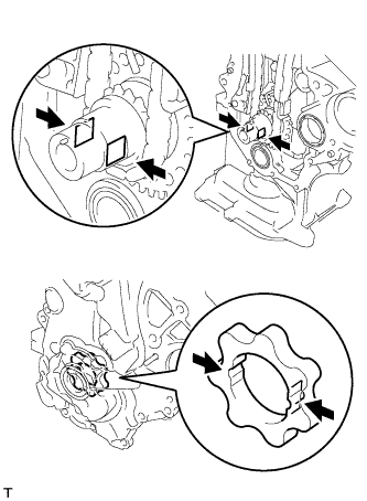
Install 2 new O-rings to the cylinder block sub-assembly and the oil pan sub-assembly.
Apply seal packing to the oil pump assembly, cylinder head sub-assembly and the cylinder block sub-assembly as shown in the illustration.
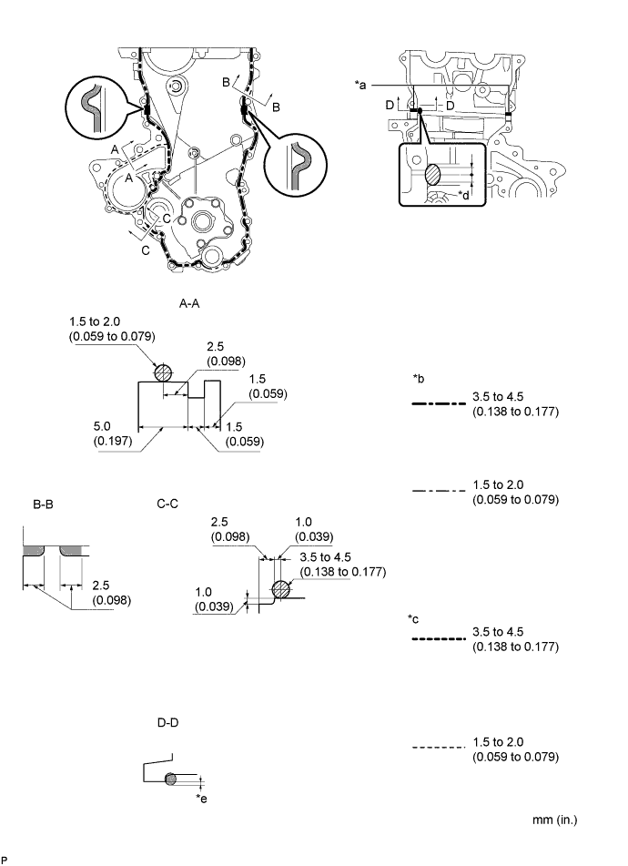
Text in Illustration *a Apply Seal Packing to the Inner Corners *b Seal Width (Other Part) *c Seal Width (Water Pump Part) *d Seal Packing Application Width 10 mm or more *e Apply enough seal packing so that it will protrude beyond the timing chain cover installation surface - - - Seal packing:
- Water pump part: Toyota Genuine Seal Packing 1282B, Three Bond 1282B or equivalent.
- Other part: Toyota Genuine Seal Packing Black, Three Bond 1207B or equivalent.
- NOTICE:
- Remove any oil from the contact surfaces.
- Install the oil pump assembly within 3 minutes and tighten the bolts and nut within 15 minutes of applying seal packing.
- Do not expose the seal to engine oil for at least 2 hours after the installation.
Align the keyway of the oil pump rotor with the rectangular portion of the crankshaft, and slide the oil pump into place.
 |
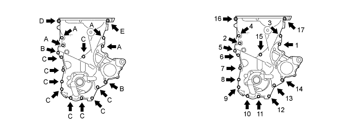
Temporarily install the oil pump assembly with the 16 bolts and the nut.
- NOTICE:
- Do not apply oil to the bolt A.
- HINT:
- Each bolt length is as follows.
- A: 30 mm (1.181 in.)
- B: 35 mm (1.378 in.)
- C: 20 mm (0.787 in.)
- E: 14 to 20 mm (0.551 to 0.787 in.), Double ended bolt
Tighten the 16 bolts and nut in the sequence shown in the illustration.
- Torque:
- Bolt A:
- 41 N*m{ 418 kgf*cm , 30 ft.*lbf }
- Bolt B:
- 12 N*m{ 122 kgf*cm , 9 ft.*lbf }
- Bolt C:
- 12 N*m{ 122 kgf*cm , 9 ft.*lbf }
- Nut D:
- 24 N*m{ 245 kgf*cm , 18 ft.*lbf }
- Bolt E:
- 24 N*m{ 245 kgf*cm , 18 ft.*lbf }
- NOTICE:
- Be careful not to disturb the seal packing.
- After installing the oil pump assembly, install the transverse engine engine mounting bracket within 10 minutes.
| 2. INSTALL TRANSVERSE ENGINE ENGINE MOUNTING BRACKET |
Install the transverse engine engine mounting bracket with the 4 bolts.
- Torque:
- 55 N*m{ 561 kgf*cm , 41 ft.*lbf }
| 3. INSTALL ENGINE WATER PUMP ASSEMBLY |
Install the water pump assembly through a new water pump gasket with the 3 bolts and 2 nuts.
- Torque:
- 12 N*m{ 122 kgf*cm , 9 ft.*lbf }
| 4. INSTALL WATER PUMP PULLEY |
Provisionally install the water pump pulley with the 3 bolts.
Using SST, hold the water pump pulley.
- SST
- 09960-10010
(09962-01000, 09963-00700)
Tighten the 3 bolts to the specified torque.
- Torque:
- 15 N*m{ 153 kgf*cm , 11 ft.*lbf }
| 5. INSTALL CAMSHAFT TIMING OIL CONTROL VALVE ASSEMBLY |
Apply a light coat of engine oil to a new O-ring and install it onto the camshaft timing oil control valve assembly.
- NOTICE:
- Do not twist the O-ring.
Install the camshaft timing oil control valve assembly with the bolt.
- Torque:
- 7.5 N*m{ 76 kgf*cm , 66 in.*lbf }
- NOTICE:
- If a component has been dropped or subjected to a strong impact, replace it.
- Make sure that the O-ring is not damaged or does not jump out of position during installation.
Connect the camshaft timing oil control valve assembly connector.
| 6. INSTALL CRANKSHAFT POSITION SENSOR |
Apply a light coat of engine oil to the O-ring.
- NOTICE:
- If reusing the camshaft position sensor, be sure to inspect the O-ring.
Install the crankshaft position sensor with the bolt.
- Torque:
- 7.5 N*m{ 76 kgf*cm , 66 in.*lbf }
- NOTICE:
- If a component has been dropped or subjected to a strong impact, replace it.
- Make sure that the O-ring is not damaged or does not jump out of position during installation.
Connect the crankshaft position sensor connector.
| 7. INSTALL CRANKSHAFT DAMPER SUB-ASSEMBLY |
Align the pin hole of the crankshaft damper with the pin and install the crankshaft damper sub-assembly.
Provisionally install the bolt.
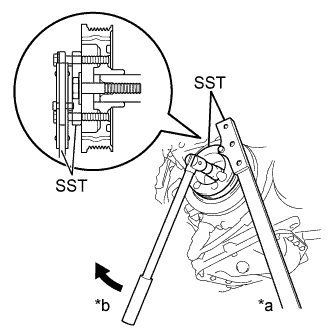
Using SST, tighten the bolt while holding the crankshaft damper sub-assembly.
Text in Illustration *a Hold *b Turn - SST
- 09213-58014
(90201-08131, 91111-50845)
09330-00021 (09330-00030)
- Torque:
- 128 N*m{ 1305 kgf*cm , 95 ft.*lbf }
- NOTICE:
- Check the SST installation positions when installing them, to avoid the SST fixing bolts from coming into contact with the oil pump assembly.
 |
| 8. INSTALL ENGINE MOUNTING INSULATOR SUB-ASSEMBLY RH |
Install the engine mounting insulator sub-assembly RH with the 4 bolts and 2 nuts.
- Torque:
- 52 N*m{ 530 kgf*cm , 38 ft.*lbf }
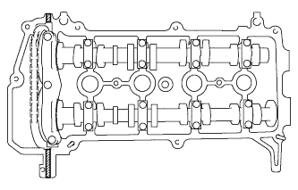
| 9. INSTALL CYLINDER HEAD COVER SUB-ASSEMBLY |
 |
 | Seal Packing |
Apply seal packing to the cylinder head as shown in the illustration.
- Seal packing:
- Toyota Genuine Seal Packing Black, Three Bond 1207B or equivalent
- NOTICE:
- Remove any oil from the contact surfaces.
- Install the cylinder head cover within 3 minutes and tighten the bolts within 15 minutes after applying seal packing.
- Do not start the engine for at least 2 hours after the installation.
Install the cylinder head cover sub-assembly with the 9 bolts, 2 nuts and 2 seal washers.
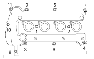 |
Tighten the 9 bolts and 2 nuts in the sequence shown in the illustration.
- Torque:
- 10 N*m{ 102 kgf*cm , 7 ft.*lbf }
Install the wire harness bracket with the bolt.
- Torque:
- 13 N*m{ 130 kgf*cm , 9 ft.*lbf }
Connect the connector and 4 wire harness clamps and connect the engine wire harness.
Connect the 4 fuel injector connectors.
| 10. CONNECT FUEL VAPOR FEED HOSE ASSEMBLY |
Connect fuel vapor feed hose assembly.
| 11. CONNECT VENTILATION HOSE |
Connect the ventilation hose.
| 12. INSTALL NO. 1 IGNITION COIL |
Install the 4 No. 1 ignition coils with the 4 bolts.
- Torque:
- 9.0 N*m{ 92 kgf*cm , 80 in.*lbf }
- NOTICE:
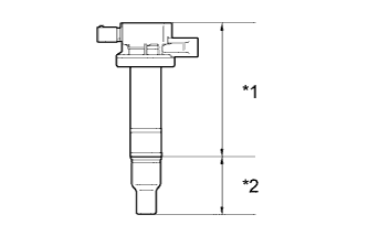
- If the body or cap of the ignition coil is dropped or subjected to a strong impact, replace the ignition coil with a new one.
Text in Illustration *1 Body *2 Cap - HINT:
- Perform "Inspection After Repairs" after replacing the ignition coil assembly (Click here).
Connect the 4 No. 1 ignition coil connectors.
| 13. INSTALL GENERATOR ASSEMBLY |
| 14. CONNECT CABLE TO NEGATIVE BATTERY TERMINAL |
- Torque:
- 5.4 N*m{ 55 kgf*cm , 48 in.*lbf }
| 15. ADD ENGINE OIL |
Add fresh engine oil.
- Standard Oil Grade (for USA, Canada):
Oil Grade Oil Viscosity (SAE) ILSAC GF-5 multigrade engine oil 5W-30
- Standard Oil Grade (for Mexico):
Oil Grade Oil Viscosity (SAE) API grade SL "energy- conserving", SM "energy- conserving", SN "resource-conserving", or ILSAC multigrade engine oil - 5W-30
- 10W-30
API grade SL, SM or SN multigrade engine oil - 15W-40
- 20W-50
- 5W-30
- Standard Oil Capacity:
Item Capacity Drain and refill with oil filter change 3.7 liters (3.9 US qts, 3.3 Imp. qts) Drain and refill without oil filter change 3.4 liters (3.6 US qts, 3.0 Imp. qts) Dry fill 4.1 liters (4.3 US qts, 3.6 Imp. qts)
Install the oil filler cap sub-assembly.
| 16. ADD COOLANT |
Tighten the cylinder block drain cock plug and the radiator drain cock plug.
- Torque:
- 13 N*m{ 133 kgf*cm , 9.6 ft.*lbf }
Pour engine coolant into the radiator assembly until it is full.
- Standard capacity:
- 5.0 liters (5.3 US qts, 4.4 Imp. qts)
- NOTICE:
- Do not substitute water for coolant.
- HINT:
- Use of improper engine coolant may damage the engine coolant system.
- Use only Toyota Super Long Life Coolant or similar high quality ethylene glycol based non-silicate, non-amine, non-nitrite, and non-borate engine coolant with long-life hybrid organic acid technology (coolant with long-life hybrid organic acid technology consists of a combination of low phosphates and organic acids).
Check the coolant level inside the radiator assembly by squeezing the No. 2 radiator hose and the No. 3 radiator hose several times by hand. If the coolant level goes down, add engine coolant.
Install the water filler cap sub-assembly securely.
Slowly pour coolant into the radiator reservoir until it reaches the FULL line.
Bleed air from the cooling system.
Warm up the engine until the thermostat opens.
While the thermostat is open, circulate the coolant for several minutes.- HINT:
- The thermostat open timing can be confirmed by pressing the No. 2 radiator hose by hand, and checking when the coolant starts to flow inside the hose.
Maintain the engine speed at 2500 to 3000 rpm.
Press the No. 2 radiator hose and No. 3 radiator hose several times by hand to bleed air.
- CAUTION:
- When pressing the radiator hoses:
- Wear protective gloves.
- Be careful as the radiator hoses are hot.
- Keep your hands away from the radiator fan.
Stop the engine and wait until the coolant cools down.
If the coolant level is below the full level, perform steps (b) through (g) again and repeat the operation until the coolant level stays at the full level.
Recheck the coolant level inside the radiator reservoir tank assembly. If it is below the full level, add coolant.
| 17. INSPECT ENGINE OIL LEVEL |
Warm up and stop the engine, and then wait for 5 minutes.
Check that the engine oil level is between the low level and full level marks on the engine oil level dipstick.
If low, check for leakage and add oil up to the full level mark.- NOTICE:
- Do not fill with engine oil above the full level mark.
- HINT:
- A certain amount of engine oil will be consumed while driving. In the following situations, oil consumption may increase, and engine oil may need to be refilled in between oil maintenance intervals.
- When the engine is new, for example directly after purchasing the vehicle or after replacing the engine.
- If low quality oil or oil of an inappropriate viscosity is used.
- When driving at high engine speed or with a heavy load, (when towing, or), when driving while accelerating or decelerating frequently.
- When leaving the idling for a long time, or when driving frequently through heavy traffic.
- When judging the amount of oil consumption, keep in mind that the oil may have become diluted, making it difficult to judge the true level accurately.
| 18. INSPECT FOR OIL LEAK |
| 19. INSPECT FOR COOLANT LEAK |
- CAUTION:
- To avoid the danger of being burned, do not remove the water filler cap sub-assembly while the engine and radiator assembly are still hot. Thermal expansion will cause hot engine coolant and steam to blow out from the radiator assembly.
Fill the radiator assembly with engine coolant, then attach a radiator cap tester.
Text in Illustration *1 Radiator Cap Tester
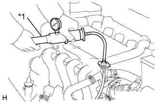 |
Pump the tester to 137 kPa (1.4 kgf/cm2, 19.9 psi), then check that the pressure does not drop.
If the pressure drops, check the hoses, radiator assembly and water pump assembly for leakage. If there are no signs or traces of external engine coolant leakage, check the heater core, cylinder block and head.
| 20. INSTALL NO. 2 CYLINDER HEAD COVER |
Install the No. 2 cylinder head cover with the 4 nuts.
- Torque:
- 7.0 N*m{ 71 kgf*cm , 62 in.*lbf }
| 21. INSTALL ENGINE UNDER COVER RH |
Install the engine under cover RH to the vehicle with the 2 bolts and the 2 screws.
- Torque:
- 5.0 N*m{ 51 kgf*cm , 44 in.*lbf }
| 22. INSTALL ENGINE UNDER COVER LH |
Install the engine under cover LH to the vehicle with the 3 bolts and the 4 screws.
- Torque:
- 5.0 N*m{ 51 kgf*cm , 44 in.*lbf }
| 23. INSTALL FRONT WHEEL RH |
- Torque:
- 103 N*m{ 1050 kgf*cm , 76 ft.*lbf }