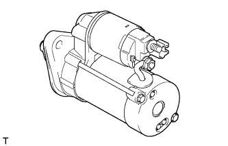
STARTER (for Sedan for Cold Area Specification Vehicles) > INSPECTION |

| 1. INSPECT STARTER ASSEMBLY |
 |
- CAUTION:
- Perform each of the following tests within 3 to 5 seconds to prevent the coil from burning out.
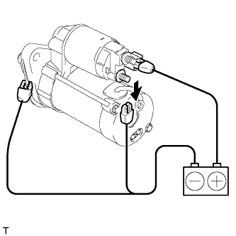
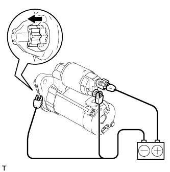
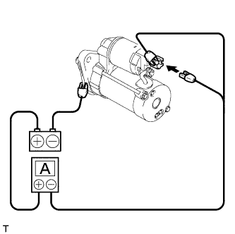
Perform pull-in / holding test.
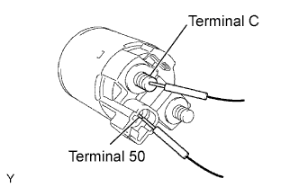
Disconnect the lead wire from terminal C.
Connect the battery to the magnet switch body as shown in the illustration. Then check that the clutch pinion gear moves outward.
If the result is not as specified, replace the magnet switch body.Disconnect the negative (-) lead from terminal C. Check that the pinion gear remains extended.
If the result is not as specified, replace the magnet switch body.Disconnect the negative (-) lead from the starter body. Check that the clutch pinion gear returns inward.
If the result is not as specified, replace the magnet switch body.
 |
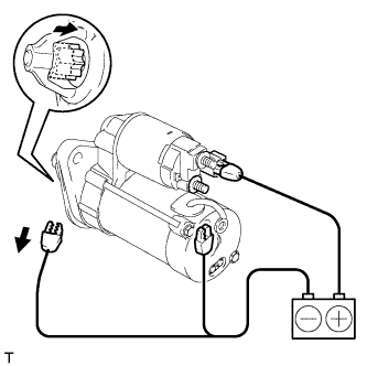
Perform operation test without load.
Connect the lead wire to terminal C.
- Torque:
- 9.8 N*m{ 100 kgf*cm , 87 in.*lbf }
Clamp the starter in a vise.
Connect the battery and ammeter to the starter as shown in the illustration.
Check that the starter rotates smoothly while the pinion gear is extended. Then measure the current.
- Standard current:
- 90A or less at 11.5V
| 2. INSPECT STARTER ARMATURE ASSEMBLY |
Inspect the commutator for open circuits.
Using an ohmmeter, check the resistance between the segments of the commutator.
- Standard resistance:
- 1Ω or lower
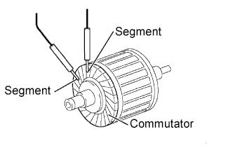 |
Inspect the commutator for ground.
Using an ohmmeter, check the resistance between the commutator and armature coil core.
- Standard resistance:
- 10 kΩ or higher
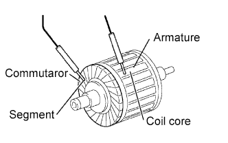 |
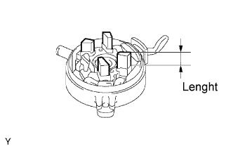
Inspect the commutator surface for dirt and burns.
If the surface is dirty or burnt, restore it with 400-grit sandpaper.
Using vernier calipers, measure the commutator length.
- Standard length:
- 3.1 mm (0.122 in.)
- Maximum length:
- 3.8 mm (0.150 in.)
 |
| 3. INSPECT STARTER COMMUTATOR END FRAME ASSEMBLY |
 |
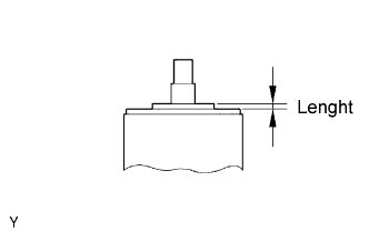
Using vernier calipers, measure the brush length.
- Standard length:
- 9.0 mm (0.354 in.)
- Minimum length:
- 4.0 mm (0.158 in.)
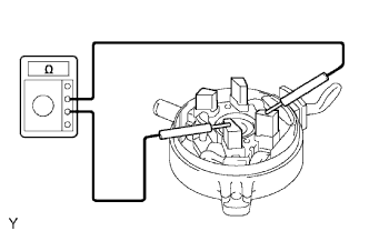
Inspect the brush holder.
Using an ohmmeter, check the resistance between the positive (+) and negative (-) brushes.
- Standard resistance:
- 10 kΩ or higher
 |
| 4. INSPECT STARTER CENTER BEARING CLUTCH SUB-ASSEMBLY |
Inspect the gear teeth on the planetary gear, internal gear and starter clutch for wear and damage.
If damaged, replace the starter planetary gear or starter center bearing clutch sub-assembly. Also check the starter planetary gear for wear or damage.
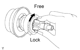
Inspect the starter clutch.
Rotate the clutch pinion gear clockwise and check that it turns freely. Try to rotate the clutch pinion gear counterclockwise and check that it locks.
If necessary, replace the starter center bearing clutch sub-assembly.
 |
| 5. INSPECT MAGNET SWITCH BODY |
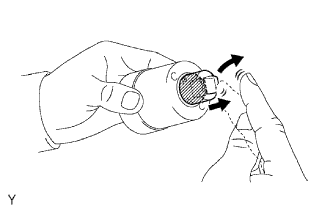 |
Inspect the plunger.
Push in the plunger and check that it returns quickly to its original position.
If necessary, replace the magnet switch body.
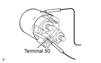
Inspect the pull-in coil for open circuits.
Using an ohmmeter, check the resistance between terminals 50 and C.
- Standard resistance:
- 1Ω or lower
 |
Check whether the holding coil has an open circuit.
Using an ohmmeter, check the resistance between terminal 50 and the magnet switch body.
- Standard resistance:
- 2Ω or lower
 |