THEFT DETERRENT SYSTEM (for Hatchback) > Security Horn Circuit |

DESCRIPTION
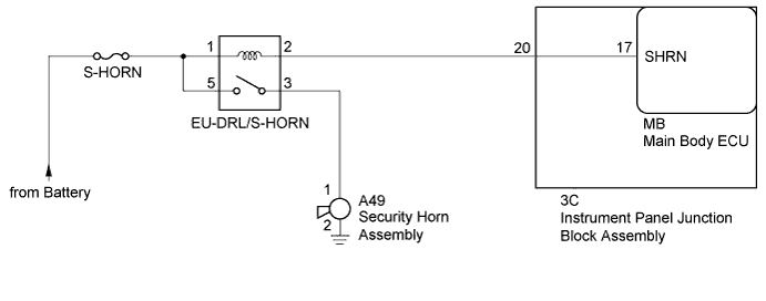
When the theft deterrent system is in the alarm sounding state, the main body ECU outputs a signal repeatedly at 0.4 second intervals, causing the security horn assembly to sound.WIRING DIAGRAM
INSPECTION PROCEDURE
- NOTICE:
- Inspect the fuses for circuits related to this system before performing the following inspection procedure.
| 1.PERFORM ACTIVE TEST USING TECHSTREAM (SECURITY HORN) |
Connect the Techstream to the DLC3.
Turn the ignition switch to ON.
Turn the Techstream on.
Enter the following menus: Body Electrical / Main Body / Active Test.
according to the display on the Techstream, perform the Active Test.
Main Body Tester Display Test Part Control Range Diagnostic Note Security Horn Security horn OFF / ON - - OK:
- The security horn sounds and stops correctly when operating it through the Techstream.
|
| ||||
| OK | ||
| ||
| 2.INSPECT SECURITY HORN ASSEMBLY |
Inspect the security horn assembly (Click here).
|
| ||||
| OK | |
| 3.INSPECT EU-DRL/S-HORN RELAY |
Remove the EU-DRL/S-HORN relay from No. 2 engine room relay block.
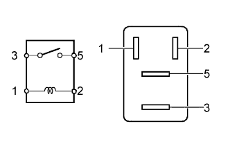 |
Measure the resistance according to the value(s) in the table below.
- Standard Resistance:
Tester Connection Condition Specified Condition 3 - 5 Battery voltage is not applied to terminals 1 and 2 10 kΩ or higher Battery voltage is applied to terminals 1 and 2 Below 1 Ω
|
| ||||
| OK | |
| 4.CHECK HARNESS AND CONNECTOR (EU-DRL/S-HORN RELAY - INSTRUMENT PANEL JUNCTION BLOCK ASSEMBLY AND SECURITY HORN) |
Disconnect the 3C instrument panel junction block assembly connector.
Disconnect the A49 security horn assembly connector.
Measure the resistance and voltage according to the value(s) in the table below.
- Standard Resistance:
Tester Connection Condition Specified Condition Relay terminal 2 - 3C-20 Always Below 1 Ω Relay terminal 3 - A49-1 Always Below 1 Ω A49-2 - Body ground Always Below 1 Ω 3C-20 - Body ground Always 10 kΩ or higher A49-1 - Body ground Always 10 kΩ or higher
- Standard Voltage:
Tester Connection Condition Specified Condition Relay terminal 1 - Body ground Always 11 to 14 V Relay terminal 5 - Body ground Always 11 to 14 V
|
| ||||
| OK | |
| 5.INSPECT INSTRUMENT PANEL JUNCTION BLOCK ASSEMBLY |
Remove the instrument panel junction block assembly (Click here).
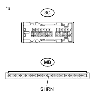 |
Measure the resistance according to the value(s) in the table below.
- Standard Resistance:
Tester Connection Condition Specified Condition 3C-20 - MB-17 (SHRN) Always Below 1 Ω
Text in Illustration *a Component without harness connected
(Instrument Panel Junction Block Assembly)
|
| ||||
| OK | ||
| ||